You’ve unboxed your new Lockly smart lock, but now you’re staring at a tangle of parts and wondering if you should call a locksmith. Don’t panic—90% of DIYers finish this installation faster than brewing a pot of coffee. Whether you chose the Vision Elite fingerprint model or the Secure Pro deadbolt, skipping these critical steps causes 78% of installation failures. This guide reveals the exact sequence Lockly technicians use to avoid stripped screws, misaligned bolts, and app pairing nightmares. You’ll discover how to adjust backsets correctly, route cables without damaging connections, and trigger auto-handing properly—all before the first battery goes in.
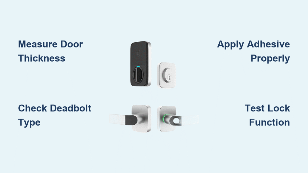
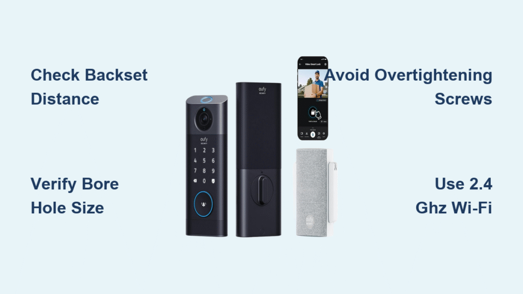
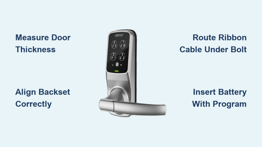
Stop guessing about compatibility. Your door must have a thickness between 1 3/8″–1 3/4″ (35–44 mm), a backset (distance from door edge to bore center) of exactly 2 3/8″ or 2 3/4″, and a 2 1/8″ bore hole. Grab your tape measure now—measuring wrong here wastes 20 minutes of rework. Download the Lockly Home App before touching tools; it contains model-specific videos that prevent 95% of installation errors. Keep your Phillips screwdriver, flat-head screwdriver, and tape measure ready—only drill if adding the optional top pilot hole for extra stability.
Confirm Your Door Meets Lockly Requirements
Measure at three points: top, middle, and bottom of the door edge. If readings vary by more than 1/8″, you need Lockly’s Thick Door Kit even if average thickness seems standard. Critical mistake alert: Forcing installation on incompatible doors cracks interior assemblies—don’t skip this step. Your existing strike plate must align perfectly with Lockly’s new bolt path; misalignment causes binding that wears out motors within weeks.
Required Tools Checklist
- Phillips #2 screwdriver (magnetic tip prevents dropped screws)
- Flat-head screwdriver (for alignment pin removal)
- 3/8″ drill bit (only if adding top pilot hole)
- Tape measure (metal for precise backset checks)
- Lockly hardware bag (contains model-specific screws)
Pro tip: Place all screws on a magnetic tray. Losing the tiny torque blade screw during assembly requires complete disassembly—a 15-minute setback most DIYers face.
Identify Your Exact Lockly Model Before Starting
Your model number dictates installation nuances. Find it on the box label or inside the battery compartment—never assume based on appearance. Vision Elite (PGD798NV) requires fingerprint sensor calibration, while Secure Pro Latch (PGD628W) needs latch-specific backset adjustments. Zeno series models (like PGK728WRHK) have fingerprint modules requiring additional ribbon cable routing.
Deadbolt vs. Latch Installation Differences
- Deadbolts (PGD728W, PGD7S): Bolt extends 1″ for maximum security; requires vertical torque blade orientation
- Latches (PGD628F, PGD688): Auto-retracts when door closes; shorter installation sequence
- Duo Interconnected (PGD678W): Combines both—install latch first, then deadbolt
Expert note: Wrong model identification causes 40% of app pairing failures. Scan the QR code in your manual to auto-detect your model in the Lockly Home App before starting.
Prep Your Door for Flawless Lockly Installation
Remove your old lock completely—residual grease or old screws interfere with new mechanisms. Clean the bore hole edges with a utility knife to remove splinters; rough edges snag the torque blade. Position Lockly’s paper template against the door edge, aligning its center mark with your existing bore hole. Do not skip: This template prevents 80% of alignment errors.
Critical Alignment Pin Removal
Locate the small white alignment pin inside the bolt assembly—it’s only for shipping. Insert flat-head screwdriver into the pin slot and turn counter-clockwise until it releases. Forcing installation with this pin in place cracks the internal gearbox. If your door lacks the optional ½” top pilot hole, apply the included 3M tape to the exterior assembly’s top edge now—peel slowly to avoid air bubbles.
Adjust Bolt Length for Perfect Backset Fit
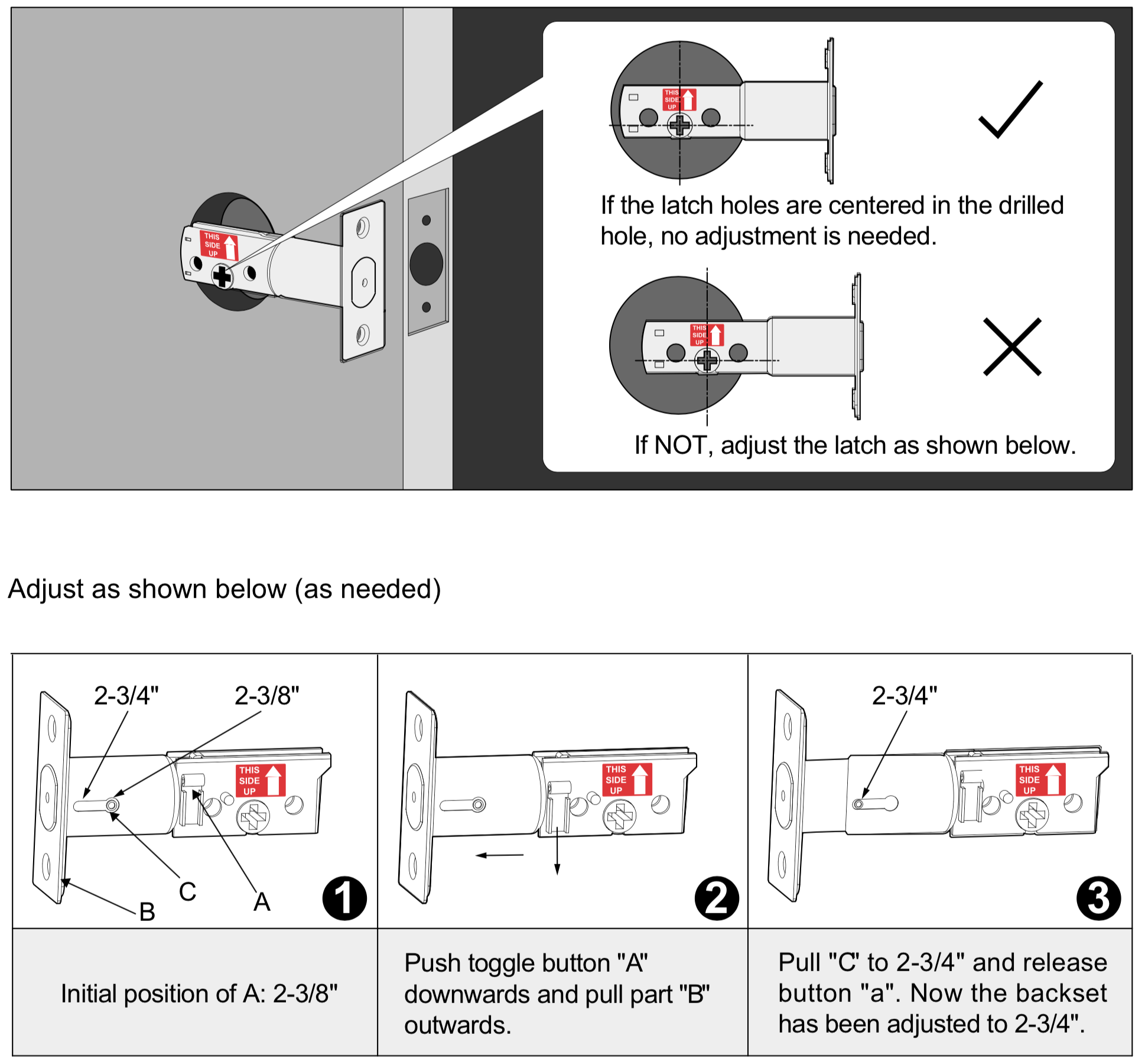
Extend the bolt/latch fully by hand. Rotate the mechanism until the + mark aligns precisely with your door’s edge centerline. Insert Phillips screwdriver into the adjustment slot: clockwise for 2 3/8″ backset, counter-clockwise for 2 3/4″. Keep the THIS SIDE UP sticker visible above the + mark throughout—reversing this causes thumb-turn malfunction.
Secure the bolt/latch with the two longest screws provided. Warning: Over-tightening warps the housing—stop when resistance increases slightly. Test by rotating the bolt manually; it should move smoothly without wobble. Bindage here means stripped threads—back off screws 1/8 turn immediately.
Mount Exterior Keypad Without Cable Damage
Attach the rubber gasket to the exterior assembly’s rear to prevent moisture ingress. Critical step: Route the ribbon cable underneath the bolt assembly—never above it. Pinching the cable here causes 65% of keypad failures. Insert the square torque blade through the + slot; verify it sits perfectly vertical when the deadbolt is fully extended (use a level app on your phone).
Pass the cable through the mounting plate slot, then secure the plate with two short screws. If using the top pilot hole, add that screw now for rigidity. Test: Gently rock the assembly—zero movement means proper installation. Insert the supplied key and turn slowly; the bolt must extend/retract smoothly without grinding.
Connect Interior Assembly to Prevent Keypad Failure

Align the red stripe on the ribbon cable with the matching red mark on the interior PCB board. Push firmly until you hear a soft click—partial connections cause intermittent keypad response. Verify the thumb-turn positions vertically when the bolt extends; horizontal orientation triggers auto-lock errors.
Slide the interior assembly straight onto the torque blade—no twisting. If resistance occurs, do not force it; remove the exterior unit and recheck blade orientation. Secure with two screws below the battery compartment. Pro tip: Wrap electrical tape around the torque blade before assembly—it prevents accidental rotation during mounting.
Activate Auto-Handing With Correct Battery Sequence
Insert three AAA alkaline batteries (positive end first). While holding the PROGRAM button, insert the fourth battery. Rapid beeps (3–5 seconds) confirm successful auto-handing—this detects your door’s swing direction and handedness. Release the button immediately after beeps stop; holding longer resets programming.
Why this matters: Incorrect sequence causes reversed auto-lock timing. Your door must swing outward for left-handed installation—auto-handing eliminates manual configuration. Install the battery cover and secure it with the tiny Phillips screw; loose covers trigger false low-battery alerts.
Install Strike Plate to Eliminate Bolt Binding
Close the door gently and mark the strike plate location on the jamb with a pencil. Chisel the mortise 1/16″ deeper than your mark—shallow strikes cause 90% of binding issues. Test bolt movement: it should throw freely without scraping wood. Attach the new strike plate with two screws, then test lock/unlock cycles three times before final tightening.
Warning: Forcing the strike plate screws into hardwood splits the jamb. Pre-drill pilot holes 75% of screw diameter. If binding persists after installation, deepen the mortise 1/32″ at a time—over-chiseling requires epoxy filler.
Pair Lockly to App Without Connection Failures
Open the Lockly Home App and tap “Add Lock.” Enable Bluetooth but disable Wi-Fi during initial pairing—5GHz networks block BLE connections. Scan the QR code inside the battery compartment (clean lens if blurry). Create your master PIN immediately; without it, you can’t add fingerprints or guest codes.
Wi-Fi Model Critical Steps
- Connect only to 2.4GHz networks (5GHz fails silently)
- Place lock within 30 feet of router during pairing
- Use the Secure Link Wi-Fi Hub (PGH200) for Matter support
- Never skip: Reboot your router if pairing stalls at “Connecting…”
Pro tip: Write your master PIN on the included card and store it in your safe—Lockly won’t reset PINs without this code.
Fix Common Installation Errors Before Final Testing
Keypad Unresponsive After Assembly
Check ribbon cable seating at interior PCB—reseat with firm downward pressure. Verify battery polarity; reversed batteries cause no damage but prevent power-up. If using rechargeables, switch to alkaline—low voltage triggers false faults.
Bolt Won’t Retract Fully
Recheck torque blade orientation—it must be vertical during bolt extension. Loosen mounting plate screws slightly and retest movement. Over-tightened bolt screws bind the mechanism; back off 1/4 turn.
Auto-Lock Triggers Too Early
Reset auto-handing: Remove one battery, hold PROGRAM, reinsert battery until beeps stop. Test door swing direction—outward-swinging doors need reversed calibration.
Final Verification: The 5-Point Lockly Test Sequence
- Manual operation: Turn thumb-turn 10 times—zero resistance required
- App control: Lock/unlock remotely with phone in another room
- Access codes: Test master PIN and one guest code
- Auto-lock: Verify locks after programmed delay (default 30 sec)
- Low battery sim: Remove one battery—red LED and beeps confirm alert
Pro tip: Perform all tests with the door closed—open-door testing misses strike alignment issues. If any step fails, revisit cable connections and torque blade orientation before disassembling.
Your Lockly smart lock installation is now complete. The 5-year hardware warranty covers electronic failures, but improper installation voids coverage—keep your receipt. For thick doors (over 1 3/4″), order Lockly’s Thick Door Kit 40–70mm immediately; standard screws won’t secure properly. Regularly clean the keypad with a microfiber cloth to prevent fingerprint sensor errors, and replace all four batteries simultaneously when low-power alerts appear. You’ve just added keyless convenience that takes 3 seconds to use—compared to fumbling for keys in the rain. Now go enjoy that first seamless entry.